Alistair Potter's RC plane tips.
Cabane and Interplane Struts for Foam Board Planes
Back to planes list. Back to homepage.
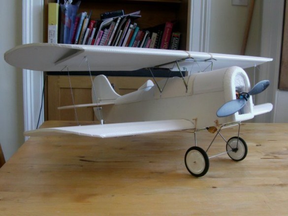
My first cabane elements appeared in my Velie Monocoupe.
This was a mix of wire, MDF (Medium Density Fibreboard), BBQ skewers (bamboo) and foam. I was able to create sufficient strength and rigidity to allow that ‘magic’ of an empty cabin space beneath the wing which has always been a great feature of this plane and its derivatives.
The basic structure beneath the surface was a simple four sided box; wire on top and to the front, MDF on part of the base and the rest from foam board. The 'box' is stiffened by its contact with the fuselage sides. A short length of BBQ skewer glued on the top of the foam board back plate allowed the connection between wire and foam with zip ties. The wing is held down by elastics looped onto skewers through the fuselage, so the forces on the glue holding this little length of skewer in place were very low.
The system has stood the test of time and is still in place in the rebuilt Morphocoupe, which is still flying.
From there it was clear the concept could be expanded, and I did this with my AVRO 539B. The key to this was a sandwiched 'foam and tongue depressor' platform that was stable enough to screw an assembled wire cabane structure onto using plastic saddle fittings.
Again, the magic airspace beneath the wing was created.
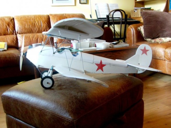
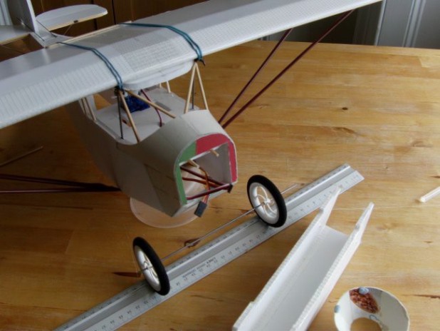
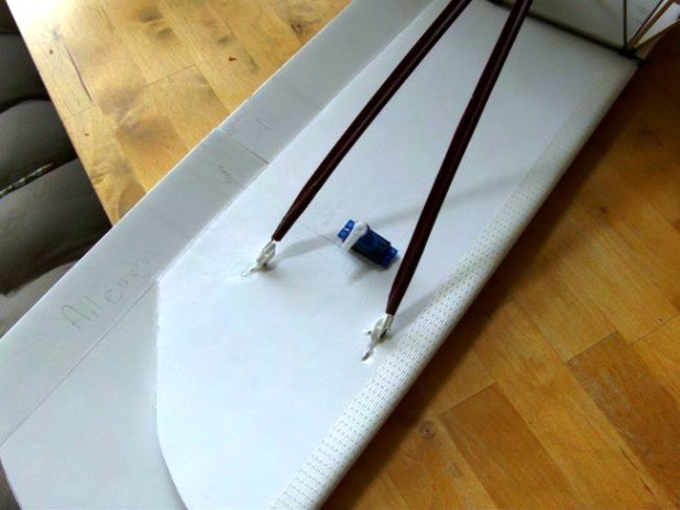
Next came another biplane build, a Polikarpov Po-2. Unlike the AVRO which has wings stacked one above the other, the Po-2 has staggered wings, which sit on triangulated components. I soon realised the screw-down saddles would be difficult to use on the Po-2 because the cabane mounts need to be fitted at the very front of the familiar box fuselage platform. There's no room for the saddle arrangement I used on the AVRO. In this picture you can see the nose start to taper down to the engine right after the front strut.
I needed another system to hold the cabane assembly down. After a bit of thought I came up with a trapped wire crossbar.
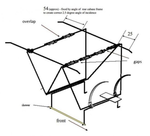
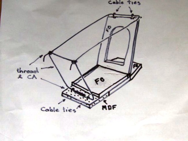
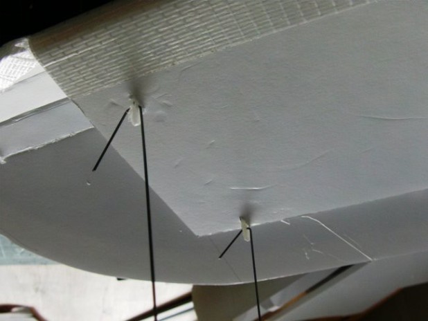
Here's my design for the Po-2 - the natural triangulation of the frames gives rigidity, and the assembly sits on the same tongue depressor platform, being held down by the zip ties connecting to cabane mount 'saddles' (trapped wire crossbars) embedded in the fuselage. I use thread and CA for my wire to wire joins.
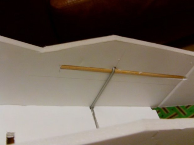
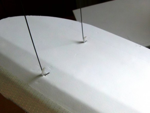
The cabane mounts (saddles) catch on skewers embedded in the fuselage sides.
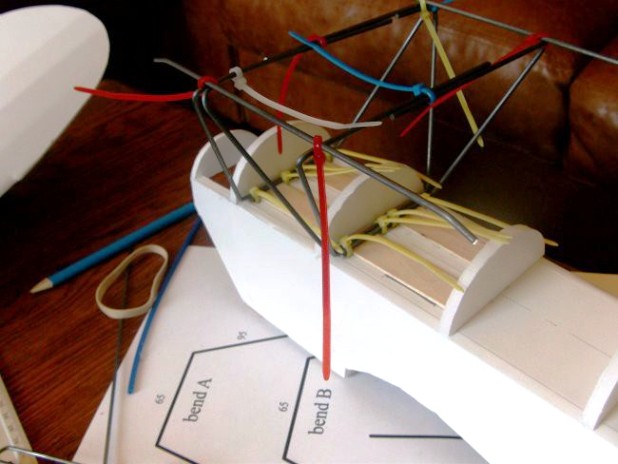
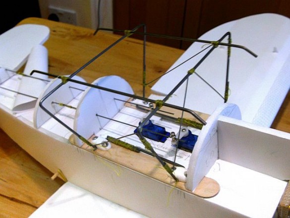
Here's a test assembly of the cabane struts onto the embedded mounts. The next stage is to tighten up the mounting zip ties and snip-off the tails, then join all the wires along the top of the frame with thread and CA.
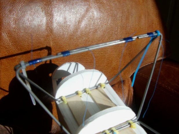
The assembly takes shape. The various forces likely to come from the wing into the box fuselage are spread into the weaker foam board by stronger elements. This is a structural solution which will endure some quite fierce abuse. Many cosmetic solutions I have seen have little inherent strength, and fold and collapse with the first firm landing or sudden stop.
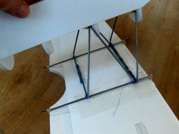
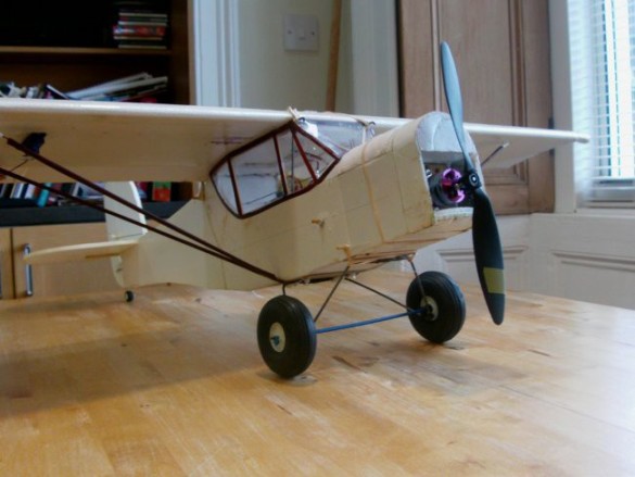
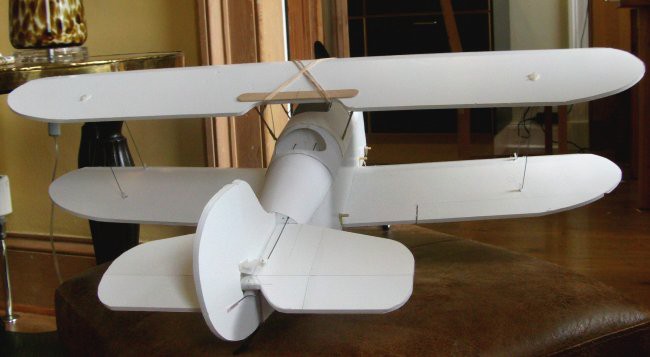
Here's the finished Po-2 assembly with the top wing in place. The final stage is to fit a centring pad (or even just corners) inside the middle rectangle of wires, so that the wing aligns correctly every time it's removed and replaced. Even if the cabane assembly is a little askew, the wing alignment can be sorted at this stage by careful positioning of the centring pads. If the wings are in the right place, people are very unlikely to notice that the cabanes aren't exactly symmetrical.
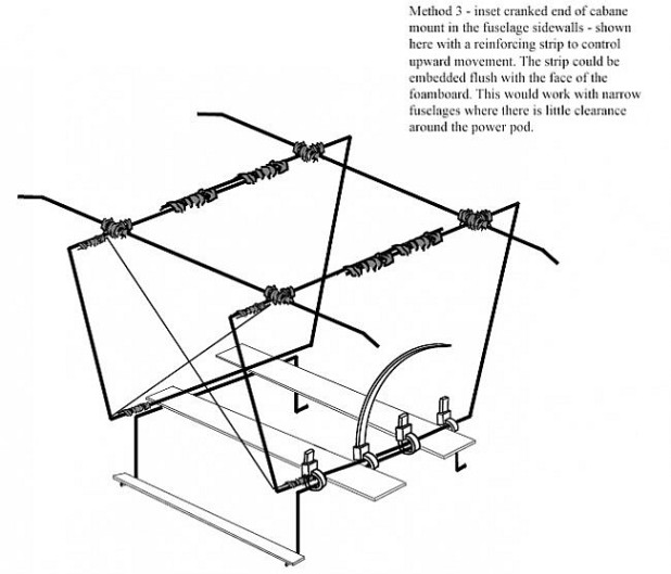
I've prepared drawings for the AVRO, and as part of that exercise I modified the cabane mounts to include this 'improved' system. This is an earlier drawing with flat side rails instead of the much simpler skewer arrangement. Unlike the Polikarpov's triangles this design is it is not self-stable and requires diagonal X-bracing for rigidity. But once it's all assembled it will be rigid enough, and simpler to fit than my original solution. I've also 'standardised ' the use of BBQ skewers sunk in the fuselage sides, replacing the flat elements shown in this drawing.
For a more rigid wire to wire join in the cabane assembly you can use wraps of thin copper wire and solder. It achieves the same effect as the thread and CA but is unlikely to release, which is a slight problem with the thread/CA join. However, having a 'break away' join in the assembly does stop damage spreading through the airframe. I've never had a thread join break, just lose connection with the wire. Easily fixed with a drip or two of thin CA. A little give and flexibility is no bad thing when absorbing the shocks of poor landings etc. I would extend this concept to the X-bracing, if the wing platform is a little springy that's not necessarily a negative. Instead of wire you could use thick thread for X-bracing, something with strength and a little give. That would add to the appearance and stiffen things up enough, but break under shock load.
The only other part of the biplane equation is the wing interplane struts. I developed a system for embedding mounting points in the wing which has stood the test of time. It was first used on my Velie Monocoupe.
This Monocoupe wing and strut assembly is still flying on the Morphocoupe. This strut is still called a cabane because it connects wing to fuselage.
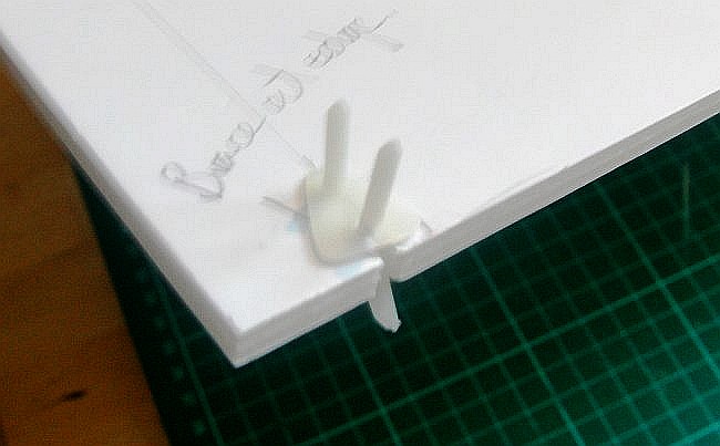
Here's the fitting system in use on the AVRO, but because it links wing to wing this is called an interplane strut.
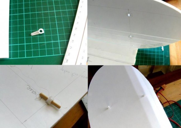
The mount is just a servo arm with a short length of BBQ skewer through the centre hole. This is slotted through the wing at the right point and glued in place. There's other simple solutions using common modelling parts…
…because the mount on the back of the top wing on my AVRO ended up so close to the edge of the bottom panel, I notched the panel and used a ratchet-fit control horn, and passed the fitting pins through the top of the wing.
Here's the pins ready to go through the top. If I remember my assembly sequence, I glued the horn in place as you see it, pressed the top panel onto the pin ends to mark the foam, and then used a bit of stiff wire to make the holes. When the wing was glued-up, the pins slipped easily through the foam and projected out the top.
Once the little ratchet plate was fitted and the protruding ends snipped-off it wasn't too obvious. You can see them just at the back there on the top wing.
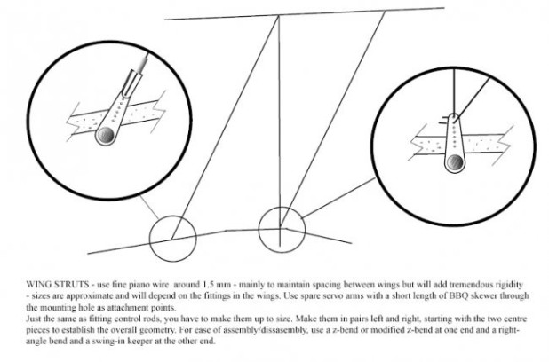
Here's the same system shown in the drawings for the PO2. By choosing a good long servo arm, more than one wire can be attached to that point on the wing. If you want you can dress up the interplane struts with BBQ skewers and insulating tape to bulk them out, which is what I did with the Velie Monocoupe. There's loads more photographs and detail in the build articles for the Monocoupe, AVRO and Po-2.
The finished drawings for the AVRO 539B, (and other biplane designs) include all the wire bending and assembly detail.
I'm still evolving the system, and if I look back at the AVRO, which just had the cabanes mounted on top of the box fuselage, it should be possible to eliminate the wire detail under the box fuselage and connect through to skewers sitting under the deck. Again, I would reinforce with a gift card or other thin flat component, to stop the skewers pulling into the underside of the deck. That's likely my next method for any future biplane builds.